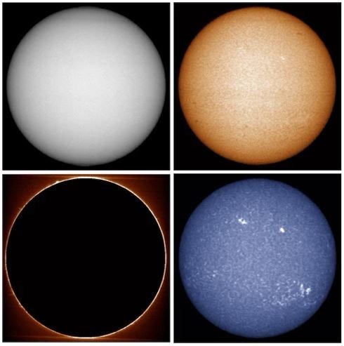
As in my prior posting, I just started building the Sol'Ex spectroheliograph (SHG) by Christian Buil at long last, after a long delay while the optics kit sat in Memphis at a FedEx warehouse. This SHG allows you to image the Sun in many different wavelengths at a higher resolution than most Ha-filtered scopes. I say image because it's not a visual scope, you "scan" the sun, let it capture video, and then process the video into an actual image. The processing software also allows you to colour the image and even mask out the disk of the Sun to highlight prominences and other features.
The optics kit from Shelyak is 405,00 € excluding VAT and was 39,31 € shipping to Canada for a total of $681.65CDN. The kit contains a pair of doublet lenses, a slit and a 2400 tr/mm holographic grating and is the most expensive component of the kit.
I started out printing the 3D printed components on my Ender 3 Pro on PETG but had a lot of problems, and the Ender was glacially slow to print as well, making troubleshooting a VERY lengthy process. My School Division got a bunch of requests for 3D printers from Bambu Labs so I decided to order an extra Bambu X1 Carbon printer to have in-house to test and make available as a remote printer for my schools. So, a lesson learned - you need a higher-end printer than the very low-end Ender 3 Pro.
The project also needed a helical focuser, which I bought domestically as a ZWO 1.25 helical focuser for $80CDN. The telescope I intend to use is a Skywatcher Evolux 62mm refractor so I bought an arrangement of neutral density filters to fine-tune the amount of flux hitting the sensor.
The first task was to embed threaded inserts into the plastic parts. This operation was much easier using an "insert" tip on my soldering iron bought from Amazon for about $15. These tips screw onto the end of the iron and are round rather than tapering to ensure the tip of the iron doesn't get stuck in the insert and pull out.
The online documentation was confusing to figure out what insert goes where (the parts list has both M4 and M3 inserts and screws listed) so I started with the biggest pieces, the two halves of the case. This confusion is amplified as the English-subtitled versions of the French assembly videos are based on the pre-printed, preassembled kit rather than the V1 self-printed video. So I needed to watch the French video with English subtitles auto-translated to get the best idea of how to proceed.
I ended up putting the inserts into the wrong component, so I called the first attempt a learning experience and reprinted the part for another go. Fortunately, I borrowed the X1 printer for the weekend so getting another part was quick. As often happens, the second attempt was vastly more successful. Taking it slowly and methodically helped a lot. The secrets:
1. Put the inserts in the right part (!)
2. Make sure the broad part of the insert into the outside of the part
3. Insert a bolt into the insert immediately after inserting, and use the bolt to ensure the part is square to the surface
4. Assemble the part immediately and use the actual bolt to make sure the insert is square and position the bolt so it engages with the thread.
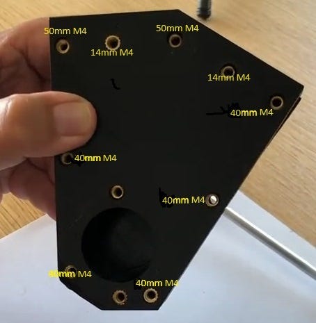
Assembling the main case was facilitated by doing one of the long 50mm bolts that the stiffener uses to stiffen the collimator block, then one of the opposite bolts, and adjusting the fit while the inserts were still hot. Putting the inserts into the right "inferior" side of the case also made the positions right every time. I did have to drill out the holes for the screws as they were too small by a mm or so but not surprising on a 3D printed hole.
One challenge with this project is interpreting the French instructions and sometimes quickly moving videos, so I'll try to add some English language instructions in this thread as best I can. Despite living in the largest French enclave in Canada after Quebec (St. Boniface in Winnipeg) and the ultimately fruitless labours of my long-suffering French teachers in school, I speak more Spanish than French
Once the case was done I tried to insert the collimator lens into the housing. The video made it quite clear that the printed housing should accept the lens and a ring when inserted should snugly hold the lens in place while leaving a bit of a gap around the housing. In practice the ring didn't protrude, and the lens rattled around in the housing, so clearly the distance between the shoulder the lens was to sit on and the end of the housing was too long, so I had to sand down the end of the housing til the lens was held snugly. This isn't a "snap-tite" level project!
Here's a running tally of what bolts go where from the parts spec.
7 x M4 length 40mm - outside 5 bolts on the main body of the SHG
2 x M4 length 50 mm - two bolts on either side of the collimator tube
4 x M4 length 30 mm - Collimator block to telescope interface
2 x M4 length 14 mm - two sides of the disk where the slit plate is mounted, threaded to collimator block
7 x M4 length 12 mm - 2 on tuner plate
2 x M3 length 16 mm - mount slit plate to slit disk
3 x M3 length 8 mm - one on grating block clip, two to hold grating block to tuner
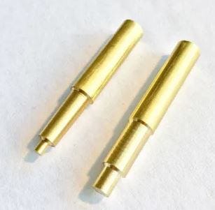
Here’s an image of most of the screw lengths required:
Assembling the "tuner" and grating holder that allows you to adjust the wavelength of the spectrum produced by the SHG was very easy, two M3 inserts in the holder bottom, one in the top, and affix the clip on top.
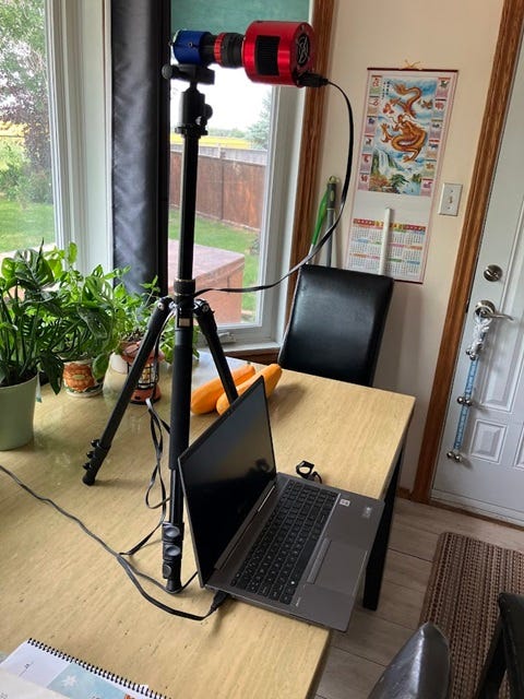
The next step the camera assembly, which is a small refracting telescope with an interface to the camera. The M42 threading produced by the X1 threaded into the ZWO Helical Focuser smoothly, without needing to refine the thread with a needle file - I continue to be impressed by this printer I printed a small sleeve that attaches to a camera tripod (see below) and mounted a UV/IT Cut filter on that since the camera is sensitive in these wavelengths but letting them through would blur the image.
After focusing the camera telescope using a printed holder available at http://www.astrosurf.com/solex/download/support_tube_objectif.stl. I needed to add a 10mm spacer (not shown) but otherwise, the image came into focus with no problem in KStars/EKOS. I locked in the focus and am carrying on with the rest of the assembly.
I carried on with mounting the expensive bits to their holders - here's the collimation block with a 10-micron slit affixed.
And then the really scary bit - mounting the grating to its holder, knowing if I messed up and touched the surface, there's no cleaning it. Luckily everything went well.
The entire unit was assembled with a 1.25" adapter on either end (I wanted to use a 2" adapter on the telescope end but I didn't have a required 2" IR/UV cut filter, and I didn't want it enough to buy one!) and plugged in - a few twiddles of the tuner later, success!
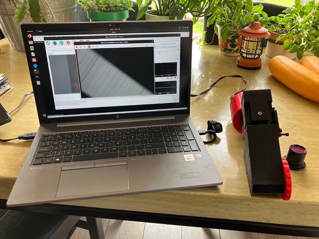
I connected the camera to my laptop (running Ubuntu Linux) and fired up KStars/EKOS, which allows streaming video from my ZWO ASI183MM camera. I had first light, flawed as it was! As you can see below I needed to rotate the camera so the spectral lines are horizontal, then work on focusing.
Next up, I’ll detail all the adjustments required and present some sample images!


