


Update: Making a MyFocuserPro2 electronic focuser
A working prototype

Once all the bits and pieces arrived for my MyFocuserPro2 project, I was able to get started on building the project.
The first task was to get the 3D design printed. After test fitting all the bits I realized my initial design was flawed, in the the motor itself required a bit of a bend on the bracket so it would mate up with the focuser axle properly. Some measuring and a bit of time on Autodesk Fusion 360 (free for hobbyists!) the result was a new model ready for printing as seen below.
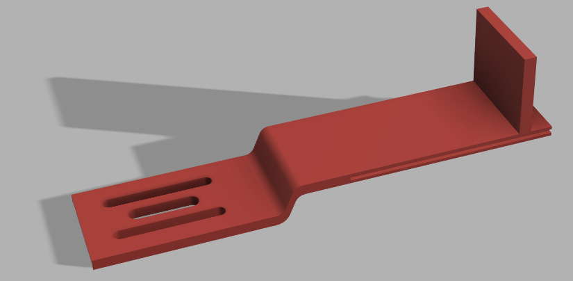
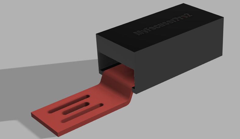
The new model had to required jog, and a slot in the frame that allows a cover to be slid onto the unit to protect the electronics from dew. With the addition of the cover the unit was ready for printing!
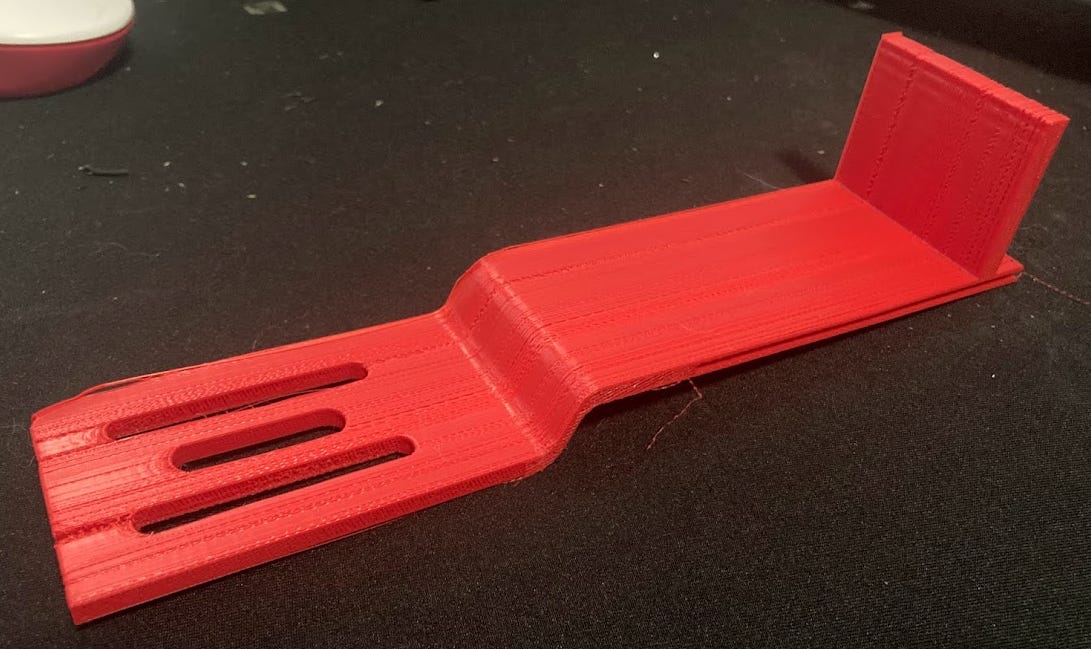
The bracket took about 8 hours to print and taxed my little Ender 3 Pro printer to it’s limits - the length of the bracket required it to be printed at a diagonal to fit on the bed and turned out to be quite sensitive to bed levelling. Even with the bed levelled, the far end of the bracket where the slots are for the screws to secure the bracket to the focuser didn’t print very well and ended up cracking in my initial prototype.
I attached the prototype to the focuser with 25mm M4 screws (the original screws being much too short, attached the circuit boards to the bracket with double-sided tape, and wired the unit up. For the prototype, I realized I had left too much space for the motor so I used a couple of pieces of spare 3D-printed junk as a spacer and refined the design.
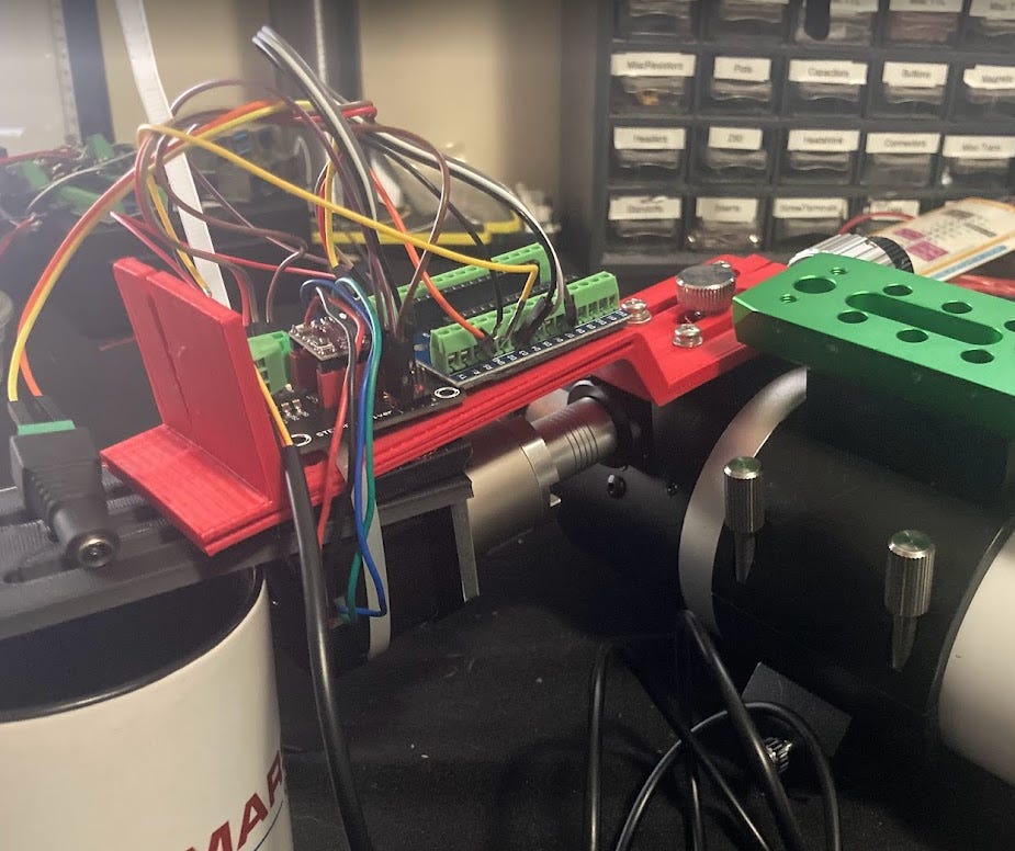
For wiring, since everything used screw terminals I used wires that had pins on one end, and either a pin or a socket on the other depending on whether it was being screwed into a connector or attached to a header pin. The result was a bit of a dog’s breakfast, but when I connected the Arduino Nano to my Raspberry Pi 400 keyboard I use in my lab, and connected 12v to the appropriate input, I was able to get the motor turning using the EKOS focuser module. Success!
I reprinted the bracket so it was a little better (marginal, I really do need a larger printer!) and also printed the cover. Where the bracket was cracked, I added a bit of model glue which firmed everything up so it was securely mounted to the focuser. I tucked the mess in under the cover and attached to the focuser and motor. Since the motor doesn’t have any screw holes left as the planetary gearbox needs them, I secured the motor to the bracket with a zip tie. The square flanges of the motor will prevent it from rotating on the bracket.
As I wired up the circuit and downloaded the sketch to be uploaded to the Arduino Nano, it became clear that the version of the circuit that included the capability for solderless connectors did not have code for the rotary encoder nor for a limit switch. After some research, I realized if I needed that capability I would need to build a custom printed circuit board so I could use the Arduino software that included these devices. A little bit more of a hassle but since the initial version worked very well, I decided to go online and order a printed circuit board so I could build out these capabilities for my focuser. No rush, since this initial prototype works well, but eventually it would be nice to have these added capabilities.
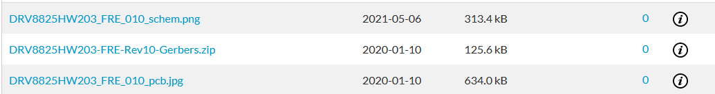
To order the circuit boards I found the correct Gerbers files on the MyFocuserPro2 site on SourceForge - these files are a standard way of representing printed circuit boards that you can have manufactured very inexpensively in China.
The layout of the PCB is fairly simple:
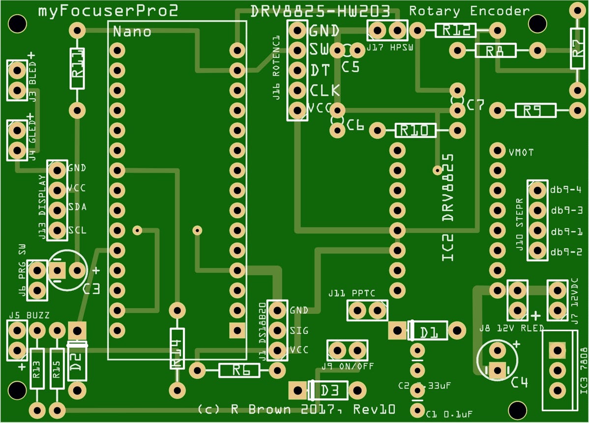
The largest components are the Nano and the DRV8825 motor driver. the rest is some resisters, diodes, LEDs, a voltage regulator to get 5v for some devices that won’t work with 12v, and connectors for the other devices. Once I build this board I’ll post a step-by-step guide to populating one of these boards. This board also has the capability to drive an LCD/LED display but since I generally use these telescopes remotely I won’t be adding this feature, although I might hook one up for testing.
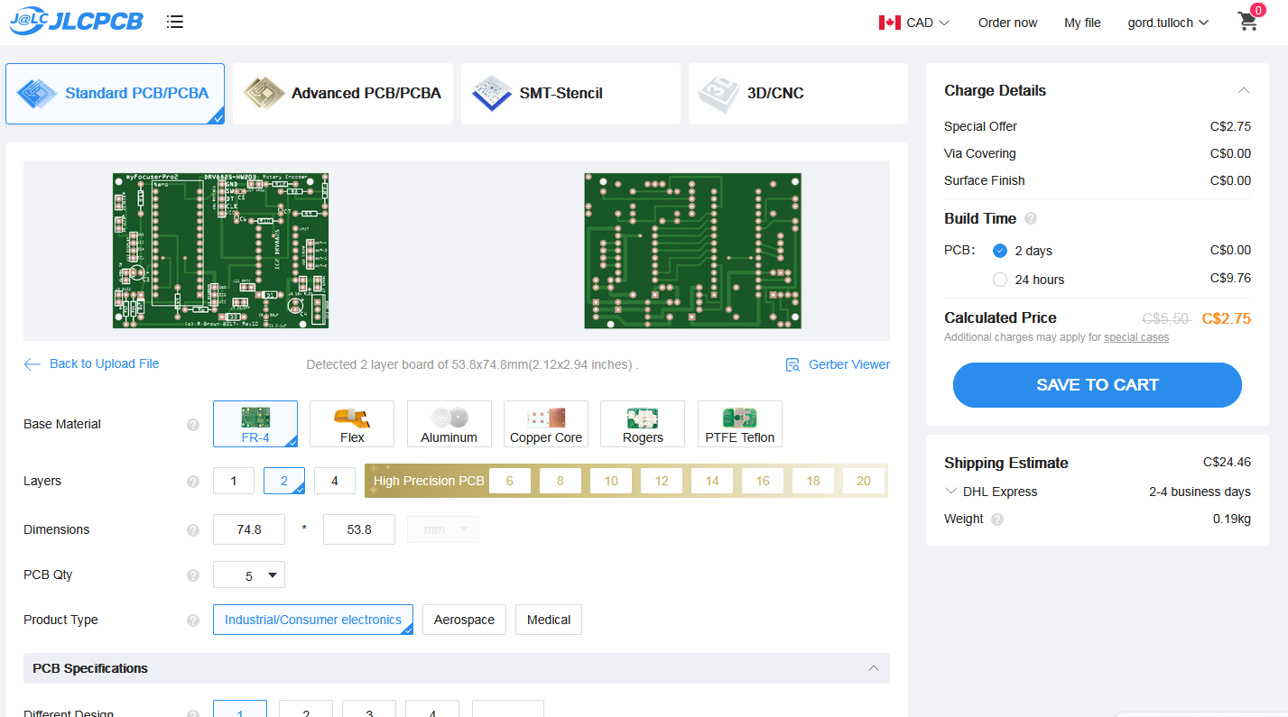
Next, I headed over to the EasyEDA website and uploaded the zip file containing the Gerber files for the correct pcb. The Gerber files pre-define all of the options so no need to touch anything else, just Save to Cart and pay. As you can see below, the cost of these boards (minimum order is 5) is extremely low. I chose slow shipping (Global Standard Direct Line, which I believe is China Post) for about $9 (9-13 days so not bad) and 10 units since they were on sale and shipping was the major cost. In the past I’ve sold extra pcb’s on Astromart however since I imagine I’ll be making a few of these focuser motors for telescope projects I’ll hang on to them.
So, while I await my printed circuit boards to build the full version of the project, my Evolux 62ED has a working motorized focuser so I can stick it out in the shed and get some use out of it!
If you’re interested in building this project feel free to use my bracket design, STL and Fusion 360 files on my website on the 3D Printing page at:
https://www.openastronomy.ca/3d-printing-for-astronomers/